Stephanie is a recent Master's degree graduate from Northwestern University.
She is passionate about creating devices which augment autonomy and enable users to explore the world in novel ways.
In particular, she is interested in product design, prototyping, healthcare and environmental conservation.
Currently, she is based in the San Francisco Bay Area.
Skills & Interests
Software Development
C Python MATLAB Mathematica ROS Git LaTeX/HTML/CSS
Simulation & Control
Lagrangian Kinematics Newton-Euler Dynamics PID Iterative Linear Quadratic Control Iterative Nonlinear Optimal Control
Design & Prototyping
Digital Painting CAD/CAM Mechatronics Laser Cutting/Scanning 3D Printing CNC Milling
Actively searching for full-time job opportunities in the fields of product design, industrial design, medical device R&D, and robotics.
Walk Off the Pages
Transforming Imagination into Art
Client:
DSGN 345 Computer Aided Manufacturing with NX
Date:
October 2017 - November 2017
Service:
Prototyping
Overview
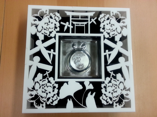
Walk Off the Pages is a multimedia art project which honors two Studio Ghibli classics: Spirited Away (2001) and My Neighbor Totoro (1988). It is a personal endeavor which I started to keep my creativity alive and my love for hands-on building satisfied. The piece was modeled in SolidWorks, then fabricated using a CNC mill and a laser cutter.
The Aluminum Centerpiece
The centerpiece is a 4” x 4” x 1.75” aluminum block which features the extruded silhouettes of Totoro and a small child dangling from a leaf. For a step-by-step description of how it was manufactured, please view the PDF linked below.
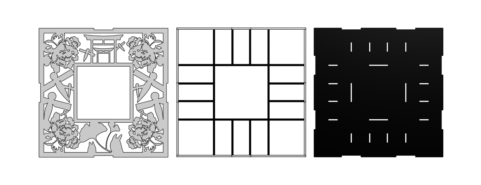
The display case is a 10” x 10” x 4” acrylic box with a cosmetic lid that highlights images from both films. It consists of 18 pieces that snugly slot together like a jigsaw puzzle. Scaffolding inside the box supports the weight of the centerpiece along 5 of its 6 faces. Balsa wood was used to verify if the smallest features could be cut. Acrylic with a thickness of 0.25” was used for the final product.
Burrowing Robot
Exploring New Mechanisms for Moving Underground
Client:
Northwestern Department of Mechanical Engineering
Date:
March 2017 - December 2017
Service:
Robophysics
Overview
Subterranean navigation and operation is important for a sundry of tasks, such as mining, construction, reconnaissance and bomb detection. Although there are numerous robots available for working in water and hard earth, fewer options exist for exploring granular media environments. The purpose of this project was to create an underground locomotor capable of following user-defined, arbitrary trajectories. This study was largely influenced by two papers: “Helical Locomotion in a Granular Medium” and “A Terradynamics of Legged Locomotion on Granular Media”.
Numerous iterations of a modular robot mounted with an auger were fabricated. Rapid, empirical tests within a loosely packed bed of poppy seeds were performed to clarify how certain auger parameters influenced the robot’s motion. A theoretical model was derived to describe how the parameters of an auger and granular material characteristics affect the amount of propulsive force generated. A final prototype was built and tested to verify the model. Suggestions for design improvements were posed based on results obtained from these experiments.
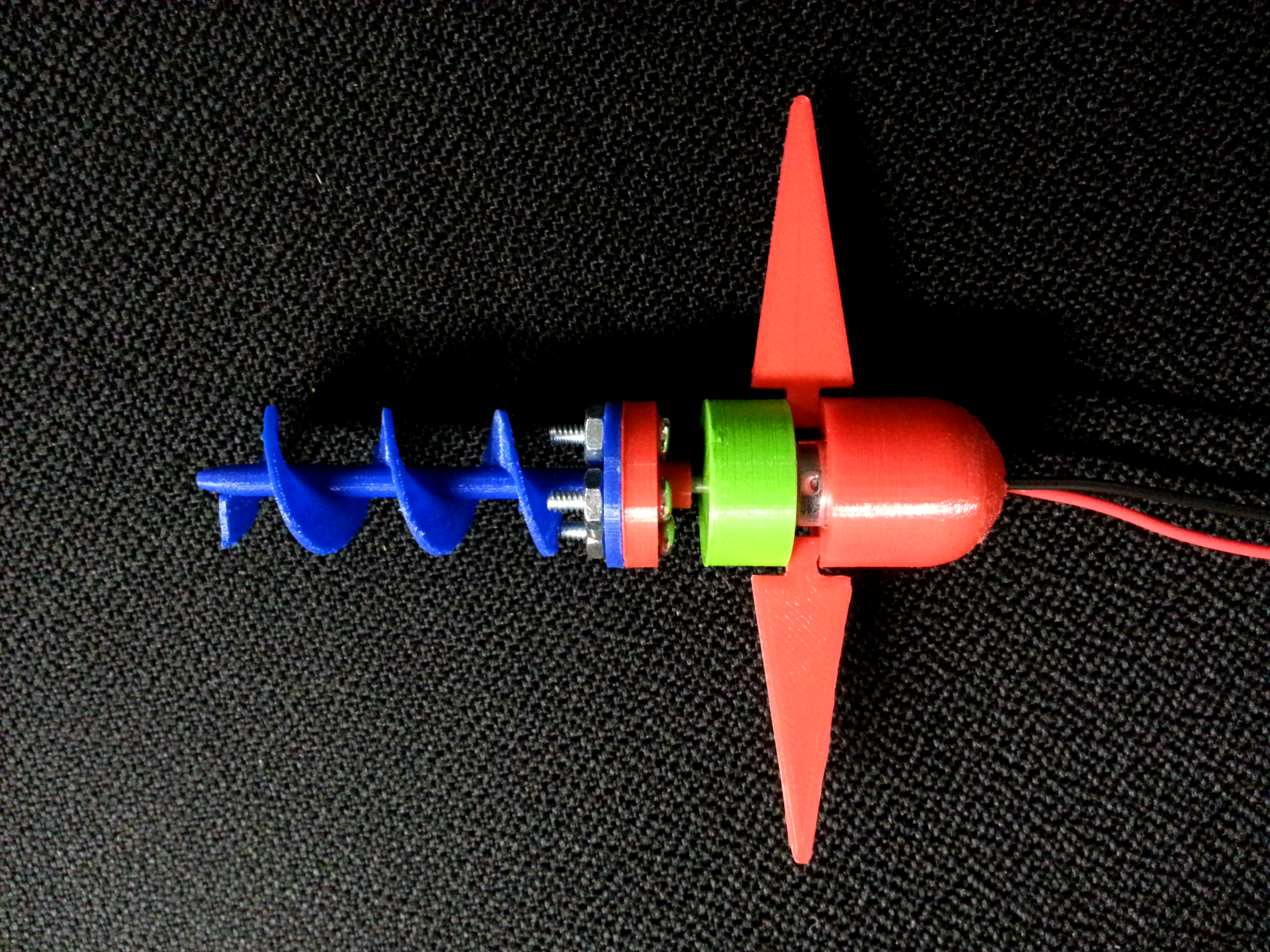
A robot with 5 main components was designed. When powered, an Archimedes screw mounted at the head of the robot spun to part granular media and pull the robot forward. This was attached to an adapter plate which fit snugly around the shaft of a DC motor. A cylindrical cap on the motor itself stopped granules from falling into an exposed gear box. Wedged inside the protective cap were wings which prevented the body of the robot from rotating with the screw. Lastly, an elongated hemispherical housing unit covered the back of the robot to shield soldered wire junctions from wear and tear. Note, a modular robot was created to make testing different combinations of screws and wing shapes easier.
The Prototyping Process
Testing Ground
A 60” x 21” x 4” bed of poppy seeds was used to characterize the behavior of the robot in granular substrates. Poppy seeds were chosen because the granules are roughly uniform in size.
Experiments Performed
For every prototype created, the following qualitative experiments were conducted:
I. Submerged swimming - The robot starts inside the poppy seed bed with its wings parallel to the bottom of the tank
II. Surface swimming - The robot starts on top of the poppy seed bed with its wings parallel to the bottom of the tank
III. Burrowing - The robot starts at an angle with the nose of the auger pointed at the surface of the poppy seed bed
Rapid Prototyping
To improve the robot’s design between trials, SolidWorks and the Ultimaker 3 3D printer were used to refine and manufacture PLA parts.
Dr. Paul Umbanhowar Dan Lynch | Thank you for being an excellent voice of reason and a great sounding board for bouncing ideas off of!
References
[1] J E Avron, O Kenneth, and D H Oaknin. Pushmepullyou: an efficient micro-swimmer. New Journal of Physics, 7(1):234, 2005.
[2] Baptiste Darbois Texier, Alejandro Ibarra, and F Melo. Helical locomotion in granular media. 119, 07 2017.
[3] D P Germann and J P Carbajal. Burrowing behaviour of robotic bivalves with synthetic morphologies. Bioinspiration & Biomimetics, 8(4):046009, 2013.
[4] Chen Li, Tingnan Zhang, and Daniel I. Goldman. A terradynamics of legged locomotion on granular media. Science, 339(6126):1408–1412, 2013.
[5] Hamidreza Marvi, Chaohui Gong, Nick Gravish, Henry Astley, Matthew Travers, Ross L. Hatton, Joseph R. Mendelson, Howie Choset, David L. Hu, and Daniel I. Goldman. Sidewinding with minimal slip: Snake and robot ascent of sandy slopes. Science, 346(6206):224–229, 10 2014.
[6] Nicole Mazouchova, Paul B Umbanhowar, and Daniel I Goldman. Flipper-driven terrestrial locomotion of a sea turtle-inspired robot. Bioinspiration & Biomimetics, 8(2):026007, 2013.
[7] A G Winter, V, R L H Deits, D S Dorsch, A H Slocum, and A E Hosoi. Razor clam to roboclam: burrowing drag reduction mechanisms and their robotic adaptation. Bioinspiration & Biomimetics, 9(3):036009, 2014.
Line Following Robot
Client:
ME 433 Advanced Mechatronics
Date:
March 2017 - June 2017
Service:
Prototyping - Mechatronics
Overview
The Line Following Robot was built for the 2017 Tech Cup at Northwestern. It uses an Android application coupled with a custom PIC32 PCB to steer a differential drive vehicle around a gray racetrack. Information is transfered between the application and the microcontroller via USB communication. Aside from sending velocity commands, the phone also provides power to two N20 brushed DC gearhead motors.
The Map
This is the course that the robots competed on. Although it is not shown, a 12” wide x 12” tall plywood gate served as both the start and finish line.
Motor Control
This is a video of some preliminary motor control tests I performed using two 4-inch wheels I designed in OnShape and 3D printed in PLA. Outside the view of the camera, I am periodically sending new slider bar and switch values from a rudimentary Android application control panel to the PIC32. On the microcontroller, the slider positions are converted to PWM duty cycle percentages. The switch positions, on the other hand, are used to toggle boolean flags that dictate whether the voltage applied to the motors should be positive or negative.
Path Detection
This video shows the racetrack centerline locater working as I walk around the map. The black lines indicate where the software believes a gray path exists. The red dots mark where the midpoint of each black line is.
Hardware
Results
Overcoming Inertia
During testing, the robot would only forward when duty cycles greater than 75% were used. As a result, the car would either shoot off the road too quickly for the path recovery algorithm to find the racetrack, or not move at all. To generate higher torque at lower motor velocities, 2-inch wheels (instead of the original 4-inch ones) were used in the final design.
Lighting
The images captured by the rear phone camera sometimes looked strangely yellow. This primarily occurred whenever the car would move from a patch of shade to a sunlit region. If the transition happened during a turn, the image processing algorithm would incorrectly identify the racetrack’s location. To remedy this, only the bottom third of the camera feed was analyzed to give the phone more time to adjust to ambient light changes. OpenCV also should have been used to raise the application’s frame rate.
Related Resources
To download or read more about the Line Following Robot and other small mechatronics projects, please head on over to the stephanniec_ME433_2017 Github repository.
Acrobot Swing Optimization
Client:
ME 454 Nonlinear Optimal Control
Date:
June 2017
Service:
Simulation & Control
Overview
Coming soon!
The Optimized System in Action
Cost Function & Parameters
System Dynamics
Results
Teleoperated Robot Arm
An Intuitive Interface which Allows Human Users to Feel What Robots Feel
Client:
Northwestern MSR
Date:
January 2017 - May 2017
Service:
Software Development
Overview
Haptic perception is an intrinsic facet of the somatosensory system which grants humans the ability to discern valuable information about the shape, orientation, and texture of objects in the world. Without it, even simple motor tasks can become frustratingly difficult to perform. The lack of tactile feedback in commercially-available prosthetics and teleoperated devices is a debilitating obstacle which prevents amputees, technicians and surgeons from moving naturally and dexterously with artificial limbs.
Telehaptics is a ROS package which brings to life a basic haptic interface using a Baxter research robot and the Geomagic Touch. When the stylus of a Touch is moved, Baxter’s right arm will trace the same motions performed. If an external force is applied to the arm, the Touch will remotely apply the same forces to the user’s hand. Together, these components form a closed-loop biofeedback system which enables users to experience something akin to telekinesis.
Note, this package is also compatible with the Sawyer research robot.
The video above shows how quickly and accurately the joint velocity controller enables a 7-DOF robotic arm to track a desired pose. In this demonstration, I am using the Geomagic Touch’s stylus to manipulate a reference frame within Baxter’s task space.
Hardware
Geomagic Touch (formerly the Phantom Omni)
The Geomagic Touch is a compact motorized device which can provide up to 3 degrees of freedom of force feedback in the x, y, and z direction.
PS3 DUALSHOCK3 Controller
Baxter and Sawyer
Baxter and Sawyer are two robots developed by Rethink Robotics which sport 7-DOF anthropomorphic arms.
PS3 Controller Nodes
joystick_reference_targets.py
Subscribed topics: joy
Published topics: ref_pose
This node uses the position of the PS3 sticks to create target end-effector poses. If the user attempts to drive the arm out of the defined workspace, the generated pose is clipped to the volume boundary. As a safety precaution, new configurations are only generated when the L1 button is pressed. This ensures that the arm will not move suddenly if the controller is bumped or dropped accidentally.
This node performs inverse kinematics to find a set of joint angle velocities which will allow Baxter’s right arm to reach a particular position in space. It constantly monitors topic ref_pose to acquire the desired end-effector state. The script baxter_right_description.py provides the node with the home configuration and spatial screw axes of the right arm. These matrices are later used to derive the body Jacobian and twists for Baxter’s current configuration using the formula below:
When the pose desired is unreachable or near a singularity, using the pseudoinverse of the Jacobian to find joint velocities may cause the system to become unstable. This is because the Jacobian only uses first-order expressions to approximate end-effector movements. One work around involves using the damped least-squares (DLS) inverse of the Jacobian to compute joint velocities.
In the equation shown above, \(\dot{\theta}\) is a matrix of joint velocities while lambda represents a damping parameter. In this node, the value of lambda (0.005) was found empirically.
gripper_control.py
Subscribed topics: joy
Sawyer equivalent: sawyer_gripper_control.py
This node controls Baxter’s right gripper when the L1 button is held down. It closes the robot’s hand when the R1 button is pressed simultaneously.
Geomagic Touch Controller Nodes
omni_reference_targets2.py
Subscribed topics: /omni1_joint_states
Published topics: /run_status, ref_pose
This node uses the transform between the Touch’s stylus frame to its base frame to create target end-effector poses. It maps rotations about the Touch’s third wrist joint to rotations about the target frame’s z-axis using JointState messages read from topic /omni1_joint_states. If the user attempts to drive the arm out of the defined workspace, the generated pose is clipped to the volume boundary. As a safety precaution, new configurations are only generated when the ‘s’ start key on the keyboard has been pressed.
velocity_control.py
The velocity control script used to control Baxter with the Touch is the same as the one used by the PS3 controller.
omni_gripper_control.py
Subscribed topics: /run_status, omni1_button
This node controls Baxter’s right gripper when the controller is enabled via the ‘s’ start key. It closes the robot’s hand when the white button on the Touch’s stylus is held down.
PS3 Controls
L1 button : Hold down to enable robot movement
R1 button : Hold down to close robot end-effector
Left stick (L/R) : Horizontal movement along the Y-axis
Left stick (U/D) : Vertical movement along the Z-axis
Right stick (U/D) : Horizontal movement towards or away from user along the X-axis
Right stick (L/R) : Rotates the gripper clockwise or counterclockwise
Geomagic Touch Controls
1. Grip the stylus like you would hold a pencil with the metal tip pointed down
2. Draw in the air where you would like the robot arm to go
3. Twist the stylus to rotate the gripper
4. Hold the white button to close the gripper
Launch Files
simstate.launch |
This file brings up an rviz simulation of Baxter as well as a GUI which enables users to manipulate and view individual joint angles.
joysys.launch |
This file simultaneously launches all of the nodes needed to run the joystick velocity control demonstration on Baxter. It pulls up an rviz simulation which shows the location of the goal end-effector pose and Baxter’s movements as the arm chases down the target frame controlled by the user in real-time.
sawyer_joysys.launch |
This file performs the same actions as joysys.launch, except for Sawyer.
omnisys.launch |
This file simultaneously launches all of the nodes needed to run the Geomagic Touch velocity control demonstration on Baxter. It pulls up an rviz simulation which accurately displays where the Touch is positioned relative to Baxter in real life. It also streams the location of the goal end-effector pose and Baxter’s movements as the user drives the target frame around in real-time.
Related Resources
To download or read more about the Telehaptics ROS package, please head on over to the baxter_telehaptics Github repository.
PIC32 Control of a Brushed DC Motor was completed for the Introduction to Mechatronics course at Northwestern. For the final exam, students were asked to develop a smart motor driver which enables a brushed permanent magnet DC motor to track reference positions, velocities and torques.
A MATLAB client interface was created to relay user commands to an NU32 microcontroller board. On the PIC32 chip, these commands were interpreted by C code which used 5 switch cases, a low-frequency PID position control loop, and a nested high-frequency PI current control loop to dictate motor behavior.
The Five Motor Switch Cases
IDLE
In this mode, no voltage is sent to the motor.
PWM
In this mode, a user-defined PWM duty cycle sets the speed and direction of the motor.
ITEST
In this mode, the current controller’s ability to track 2-4 cycles of a 100 Hz, 50% duty cycle, \(\pm{200}\) mA square wave reference current is evaluated and plotted for PI gain tuning.
HOLD
In this mode, the motor moves to a user-defined position and attempts to maintain this configuration indefinitely.
TRACK
In this mode, the motor executes a desired trajectory specified by time points (in seconds) and motor positions (in degrees). As the shaft moves, readings measured by an encoder are stored and subsequently plotted for PID gain tuning.
Gain Tuning
Figure 1: Evaluation of System's Ability to Replicate a 200mA Square Wave. Blue denotes the reference square wave, while red denotes the actual current measured across the motor.
To regulate current, the best PI gains were found to be Kp = 45 mV/mA and Ki = 1.75 mV/mA. These values were determined from the test shown in Figure 1. Although some lag is present, the red curve exhibits minimal overshoot and successfully toggles between \(\pm{200}\) mA.
Figure 2: Evaluation of System's Ability to Follow a Trajectory. Blue denotes the reference cubic wave, while red denotes the actual motor positions read by the encoder.
To track position, the best PID gains were found to be Kp = -2.5 mA/deg, Ki = 0 mA/deg, and Kd = -100 mA/deg. These values were derived from the test shown in Figure 2. During testing, the motor was able to hit the correct angles roughly around the desired times. Minor overshoot occurred after 1.0s due to delayed changes in current. In hold mode, position recovery worked only when the inertial load bar was perturbed less than 1080° away from its original orientation.
Results
This video shows how the motor behaves when a -100% duty cycle, a 100% duty cycle and a 0% duty cycle are sent to the PIC32 sequentially. During testing, the motor was able to reach its maximum speed within 5 seconds.
This video shows how the motor behaves when a cubic reference trajectory is sent to the PIC32. The test trajectory (0s, 0° | 1.0s, 90° | 1.5s -45° | 2.5s, 0°) is reproduced faithfully. When the bar ceases moving, the system clearly resists when I disturb the propeller away from its final configuration.
Baxter Plays Checkers is a project which was created for the ME 495 robot part-manipulation competition at Northwestern. During the final exam, teams comprised of 4-6 students were asked to showcase a fun and original demonstration using a Baxter Research Robot to pick up and place objects.
Checkers is a ROS Python package which grants Baxter the ability to play the aforementioned game against a human opponent. The software features a 5 node network which helps Baxter autonomously recognize the state of the game, compute valid moves, and accurately transport red checkers pieces between squares using inverse kinematics and OpenCV. Below is a video of Baxter responding to a move.
To download or read more about the Checkers ROS package, please head on over to the Baxter-Checkers-ME495_2016 Github repository.
Fluorescent mRNA Biosensors for Screening Drugs
A Molecular Tool for Discovering Cardiac Hypertrophy Inhibitors
Client:
UCSD Department of Bioengineering
Date:
March 2014 - August 2016
Service:
Medical Devices
Overview
Cardiac hypertrophy refers to the enlargement and thickening of heart tissue in response to hemodynamic pressure and stress. It progresses pathologically when excessive tissue growth leads to abnormal mechanical stiffness, fibrosis, and cardiomyopathy. Current heart disease treatments are limited to expensive and sometimes invasive options. Eventually, patients either undergo pacemaker or heart transplant surgery, or are prescribed cocktails of biological inhibitors. To minimize the cost and risk of developing therapies, it would be useful to have an in vitro assay to screen for new drugs that inhibit cardiac hypertrophy. Unfortunately, no reliable high throughput assays exist.
For my senior capstone project, I created a set of mRNA biosensors that, when transfected into cells, fluorescently detects for mechanical and norepinephrine-induced stretch in cardiomyocytes. Specifically, I synthesized a molecular tool which accurately monitors miRNA expression levels in hypertrophic cells after 24 hours of applied stress.
Antiretroviral therapy (ART) is a strict drug regimen which combines multiple medications to impede HIV replication. When the treatment works, the concentration of HIV RNA in the bloodstream remains undetectable (at under 50 copies/mL). Routine viral load monitoring following the initiation of first-line ART is a recommended procedure which facilitates early detection of HIV drug resistance. It is also prohibitively expensive: a single genotyping assay can cost anywhere between $200-400, requires highly trained technicians and specialized laboratory equipment.
While these price points are affordable in developed regions, such as the U.S and Western Europe, lifelong treatment is unsustainable for patients in limited-resource settings. To compensate, doctors have been known to track less demanding hematological and immunological parameters, which oftentimes respond to the presence of drug resistance after a lengthy time delay. The lag period between ART failure and correct diagnosis is a critical problem which exposes the patient to further immune system degeneration and promotes the spread of mutant HIV strains.
To confront these challenges, VIRA was created to provide physicians at Maputo Central Hospital with an open-source alternative for screening HIV patients for ART drug resistance.
The System
The VIRA diagnostic system is a semi-automated viral load monitoring device comprised of four key units: a low-cost centrifuge, an RNA extraction fluidic system, a PCR thermocycler, and a gel electrophoresis box. It is a versatile tool which allows minimally trained technicians to rapidly and accurately perform qualitative nucleic acid tests. To screen blood samples, VIRA runs the assay described below:
1. Separate blood plasma from patient blood sample
2. Isolate RNA from blood plasma
3. Generate cDNA from extracted RNA via reverse transcription
4. Amplify trace amounts of cDNA using PCR
5. Purify PCR amplicons using clean up kits
6. Verify if amplicons obtained belong to HIV in 1% agarose gel via gel electrophoresis
The complete system costs approximately $500 ($7 per test), minimizes technician input, and is simple to troubleshoot.
The RNA Extraction Prototype
Figure 1: RNA Prototype Blueprint. Shelf 1 houses the user interface; shelf 2 protects the circuitry; shelves 3 and 4 support the fluidic network; and shelf 5 positions the vacuum manifold underneath the reagent metering line.
The RNA Extraction device is a fluidic system which semi-automates the process of isolating RNA from blood serum. It uses a network of Arduino-controlled peristaltic pumps to replicate precision pipetting, and features a hermetic vacuum manifold coupled with a solenoid valve to separate mixtures in place of a microcentrifuge. For testing purposes, prototype 1.0 was designed to be compatible with Roche’s High Pure Viral RNA Kit. Below is a slideshow of how the device has evolved over the years.
The Thermocyler
Figure 2: (L) The 2013 Thermocycler Prototype (R) The 2016 Thermocycler Prototype
VIRA’s thermocycler features a customized PCB which controls a Peltier chip that heats and cools an aluminum block. Temperature cycling is adjusted based on feedback from sensors embedded in the device. As samples loop through enzyme-specific temperature ranges, different sets of primers which target HIV’s env gene are activated. We chose env because it codes for essential viral envelope proteins (gp120 and gp41) which HIV relies on to find and invade CD4 cells.
The Gel Electrophoresis Box
Figure 3: (L) Gel Box CAD Drawing (R) The Final Gel Box Prototype
Although VIRA’s gel box mimics available electrophoresis devices, our product is unique in that the chassis comes disassembled in the form of a DIY kit. This distribution method was selected to reduce manufacturing costs, as well as provide interested members of the general public with an interactive opportunity to learn about extant medical devices and basic design techniques.
The Low-speed Centrifuge
Figure 3: The 2015 Centrifuge Prototype
The low-speed centrifuge is an auxilary tool which can be used by technicians to perform both RNA extraction and reverse transcription. The prototype includes an ABS 3D printed plate head with an anti-shear design that interfaces with a simple motor. The alpha model, which now sits in Maputo Central Hospital, is capable of applying up to 8,000 x g and runs off of a self-sufficient power source. The latter feature was added to help clinics work through power outages, which regularly occur in Mozambique.
My Role
Engineering World Health (EWH) at UCSD is an undergraduate organization that designs alternative, low-cost laboratory equipment for indigent populations. When I was a freshman, I was brought on board the VIRA design team as a member of the RNA extraction device group. As a researcher, I played a key role in developing the RNA device’s fluidic system, fabricated mechanical components, designed circuitry, and supervised software development. From 2014 to 2015, I served as the RNA team lead. Prototype 1.0 was completed just before I graduated.
Project Accolades
May 2015 | 1st Place, San Diego Social Innovation Challenge ($10,000)
May 2014 | 2nd Place, Zahn Social Venture Prize ($1,500)
Oct 2012 | 2nd Place, EWH National Design Competition ($1,000)
5x Clinton Global Initiative University
4x Recipients of UCSD’s Social Innovation Grant Funding
3x UC Global Health Day
3x Founders Day Symposium
 A robot with 5 main components was designed. When powered, an Archimedes screw mounted at the head of the robot spun to part granular media and pull the robot forward. This was attached to an adapter plate which fit snugly around the shaft of a DC motor. A cylindrical cap on the motor itself stopped granules from falling into an exposed gear box. Wedged inside the protective cap were wings which prevented the body of the robot from rotating with the screw. Lastly, an elongated hemispherical housing unit covered the back of the robot to shield soldered wire junctions from wear and tear. Note, a modular robot was created to make testing different combinations of screws and wing shapes easier.
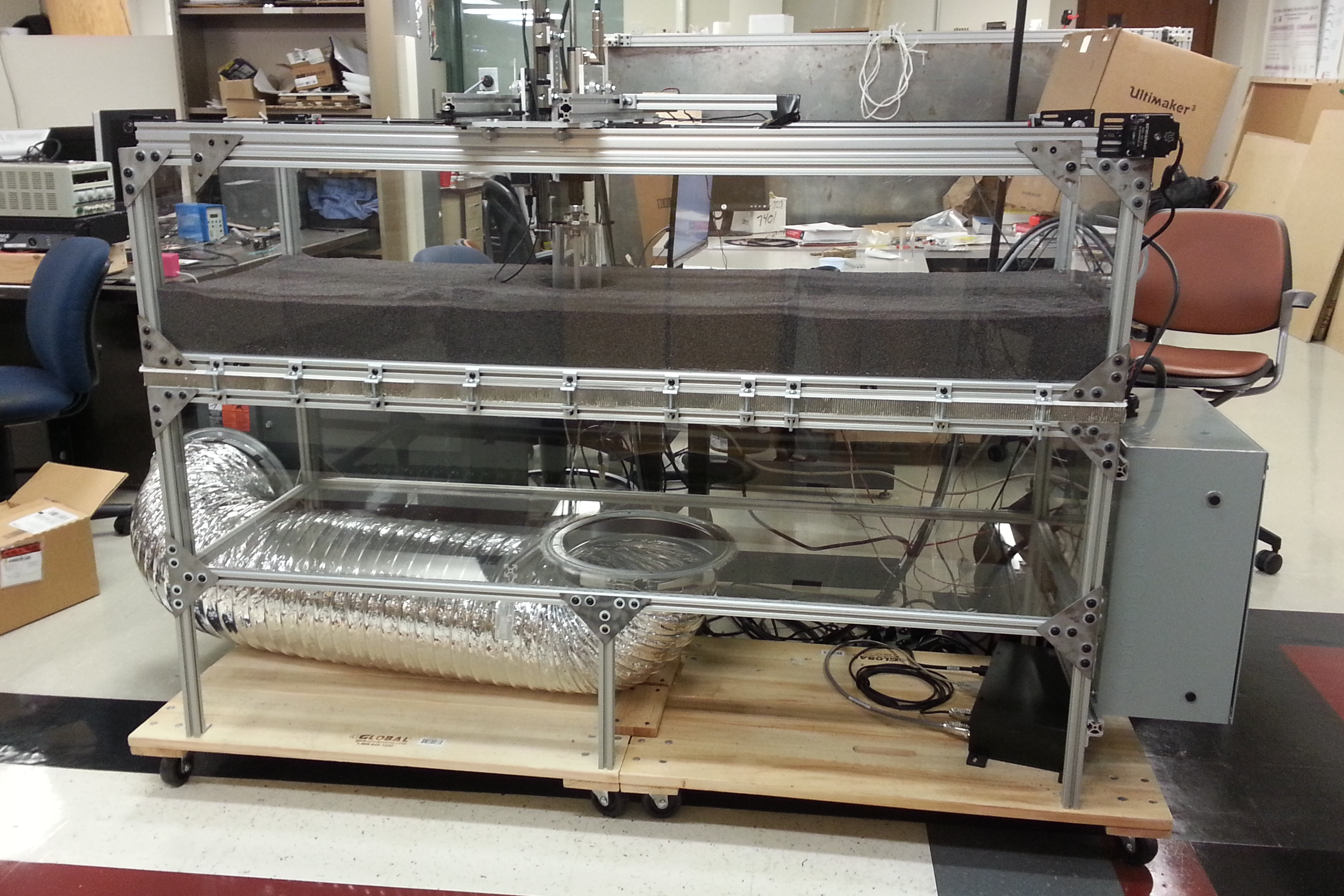
 This is the course that the robots competed on. Although it is not shown, a 12” wide x 12” tall plywood gate served as both the start and finish line.
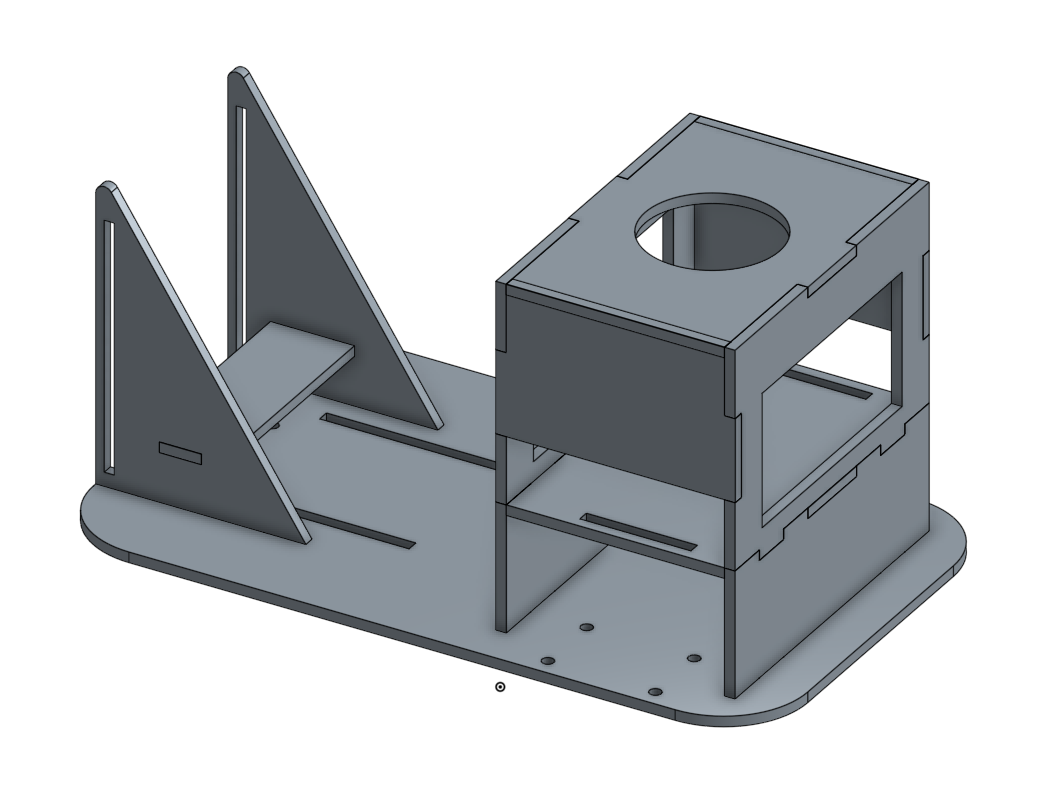
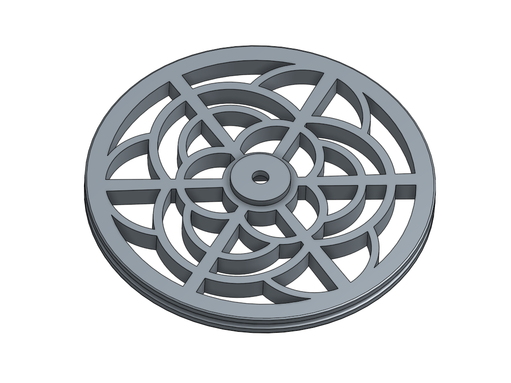
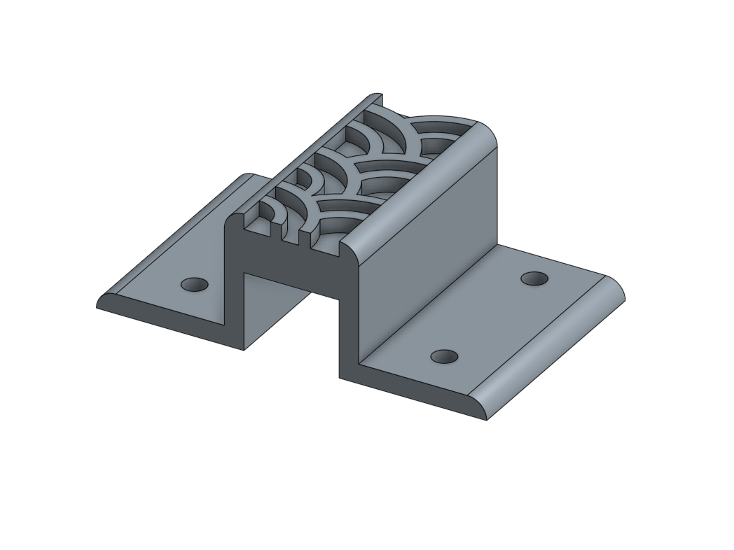
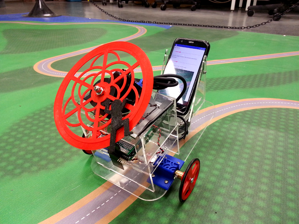
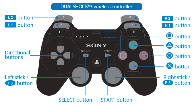
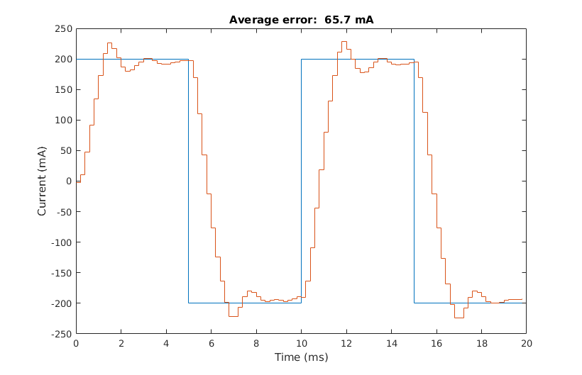
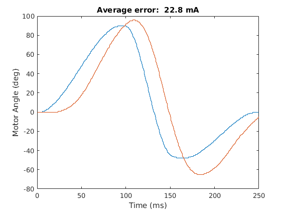
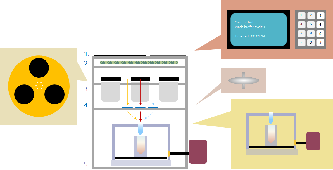
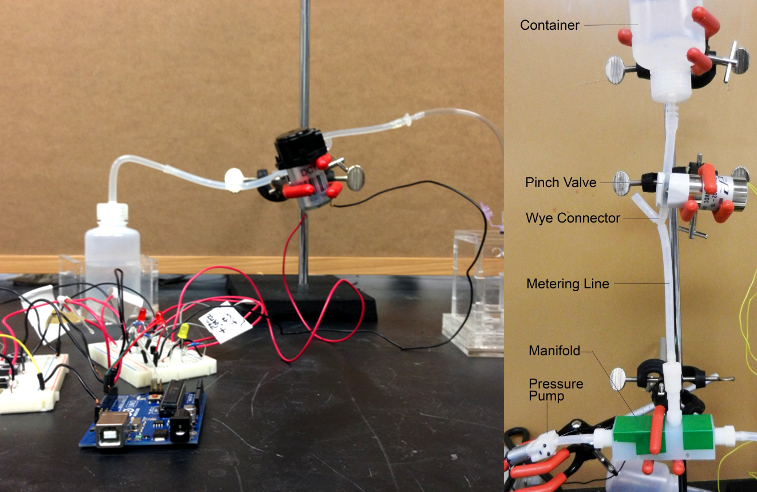
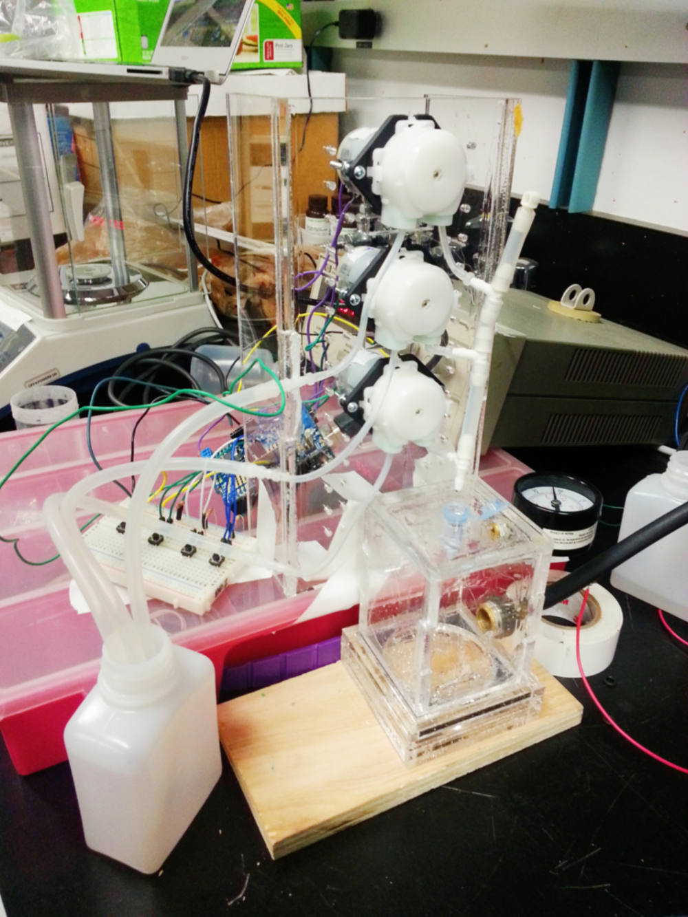
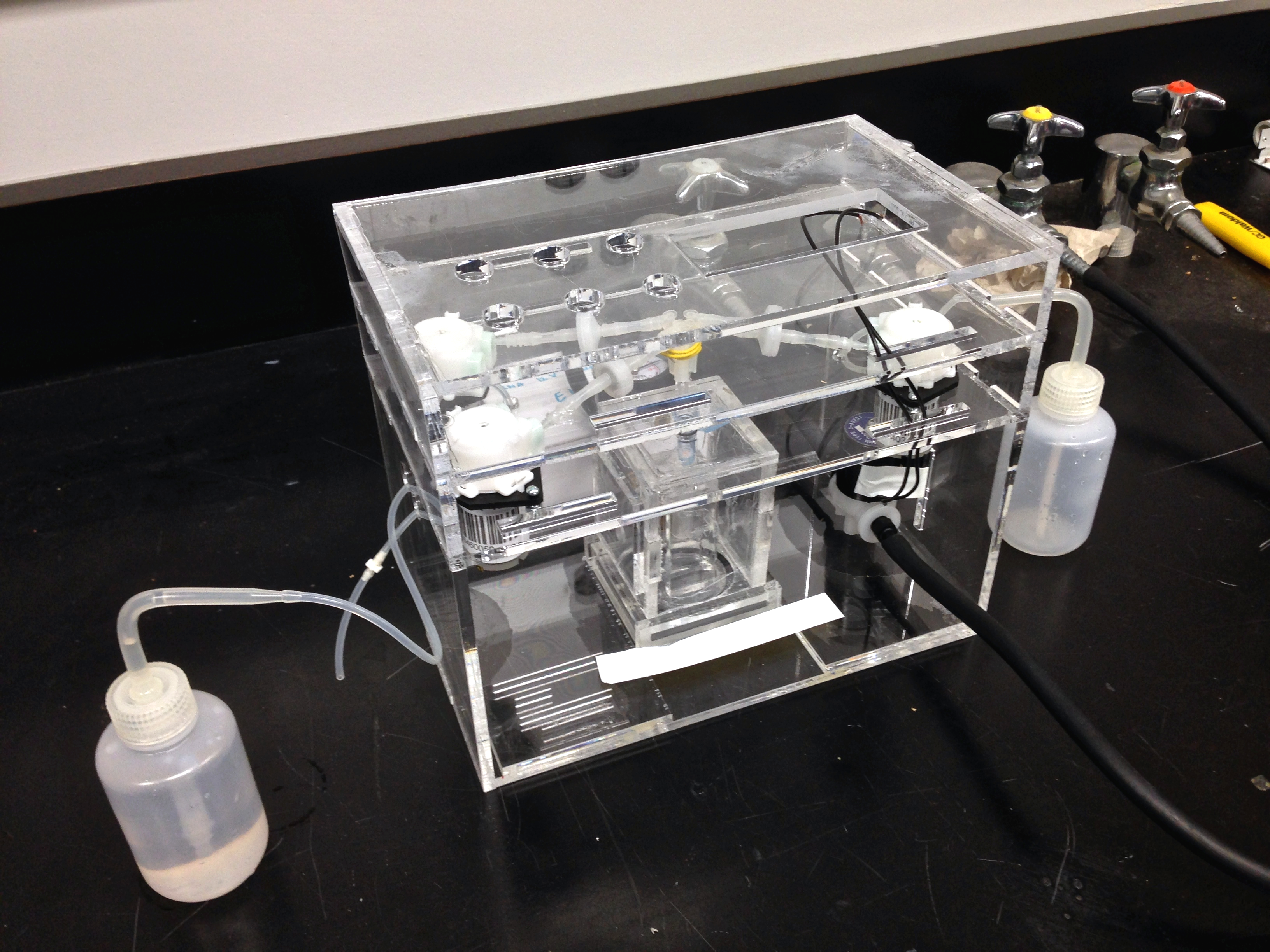
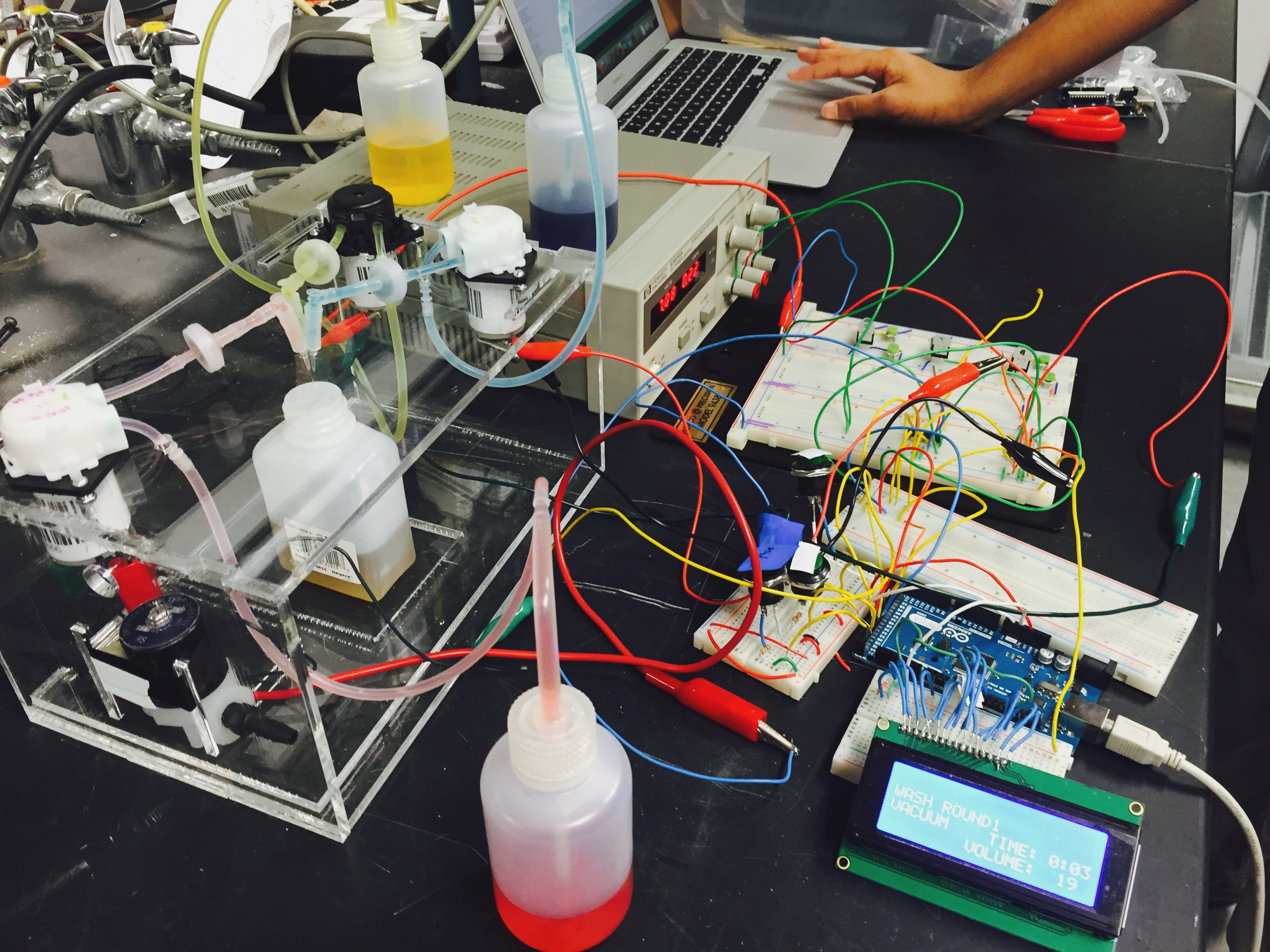
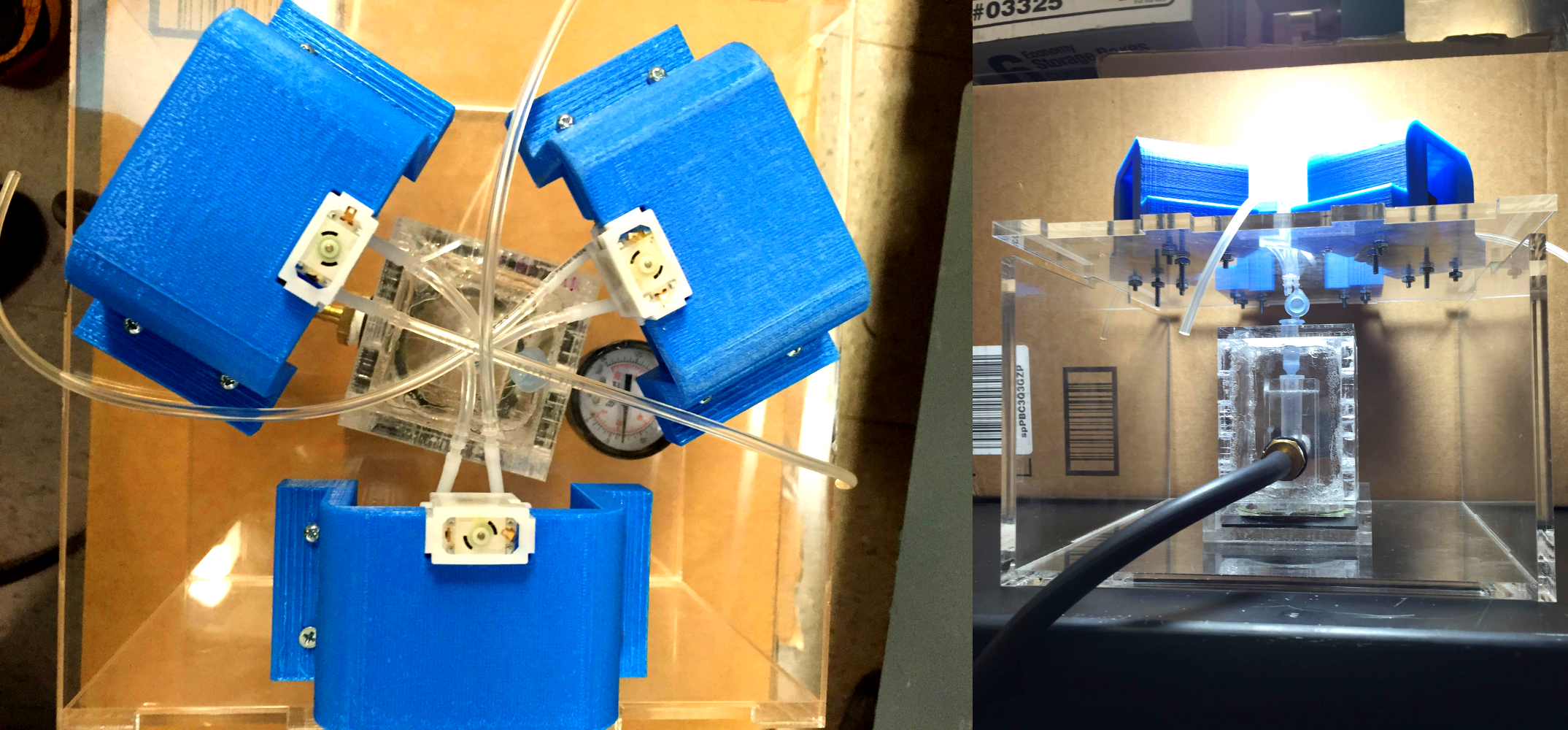
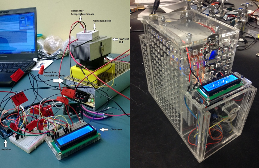
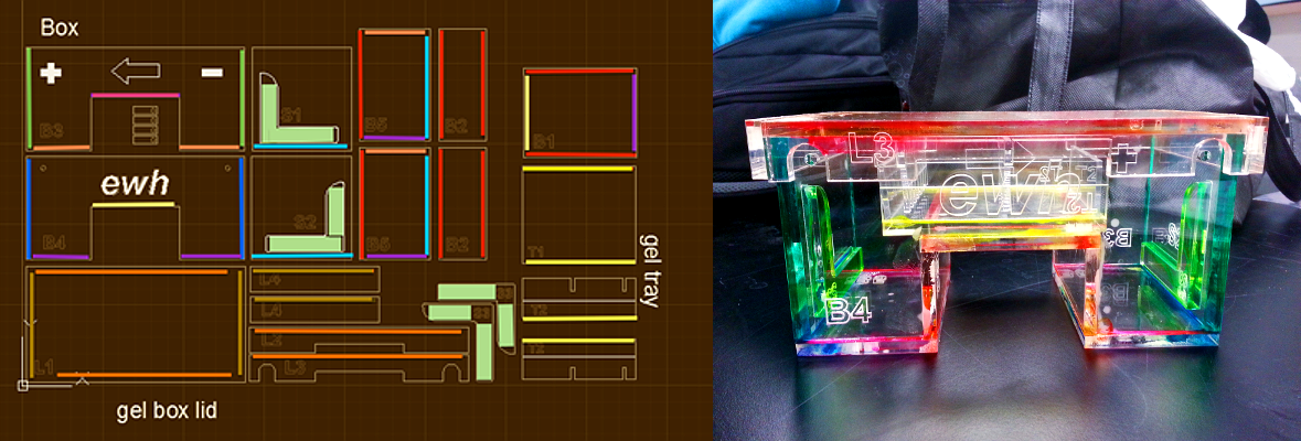
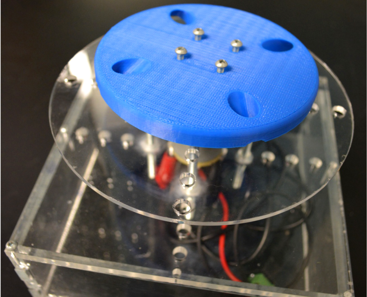 Figure 3: The 2015 Centrifuge Prototype